Icon Features
What every Visio-Cisco master carries, why, and how to use it.
Nine connection points
Every master has nine named connection points, positioned mathematically relative to the icon’s centre so any of the four cardinal directions, four diagonals, or “below the caption” anchors snap precisely:
| Name | Formula | Use |
|---|---|---|
North |
(Width × 0.5, Height × 1.1) | Lines coming down to the icon from above |
East |
(Width × 1.1, Height × 0.5) | Right-side connectors |
South |
(Width × 0.5, Height × -0.1) | Lines coming up to the icon from below |
West |
(Width × -0.1, Height × 0.5) | Left-side connectors |
NorthEast |
(Width × 1.1, Height × 1.1) | 45° anchors |
NorthWest |
(Width × -0.1, Height × 1.1) | |
SouthEast |
(Width × 1.1, Height × -0.1) | |
SouthWest |
(Width × -0.1, Height × -0.1) | |
SouthOfText |
(Width × 0.5, -12 mm) | Anchor below the caption: chain of icons in a vertical list |
The anchors sit 10% outside the icon’s bbox so a glued connector ends just outside the icon’s edge, which renders cleanly without overlap.
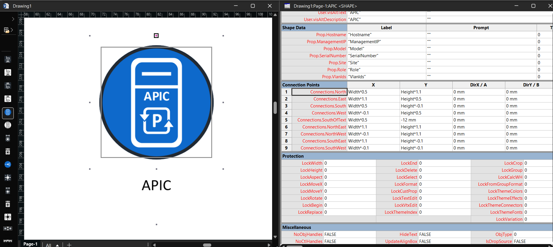
The per-master contract in Visio’s ShapeSheet: the nine named connection points and the shape-data rows, exactly as the pipeline wrote them.
Twenty-millimetre normalised size
Each icon is fit to 20 mm on its longer side, aspect preserved. This means:
- An 18 × 18 icon renders at 20 × 20 mm.
- An 18 × 14 icon renders at 20 × 15.5 mm.
- A 14 × 18 icon renders at 15.5 × 20 mm.
A drawing of fifty different network devices therefore looks like one drawing, not a collage of icons at random sizes.
Sizing is taken from the union of painted path bounding boxes, not the declared viewBox. This matters for the Cisco corpus because many icons carry generous viewBox padding that would make the artwork appear as a small dot if sizing were taken from the viewBox alone. Measuring the actual inked area ensures each icon fills its 20 mm frame.
This build is produced in two unit systems; see Metric vs US units. The 20 mm figure applies to the metric (_m) build; the US (_u) build uses the imperial equivalent.
Seven Shape Data fields
Every master ships with these seven fields ready for network metadata:
| Field | Type | Notes |
|---|---|---|
Hostname |
String | Device hostname or FQDN |
ManagementIP |
String | Primary management IP address |
Model |
String | Hardware model (e.g. Catalyst 9300) |
SerialNumber |
String | Device serial number |
Site |
String | Physical or logical site name |
Role |
String | Network role (e.g. distribution, border, leaf) |
VlanIds |
String | Comma-separated VLAN IDs or ranges |
Scripts can iterate the masters on a page and populate these from a Catalyst Center, NetBox, IPAM, or CMDB export, enabling round-trip network documentation workflows.
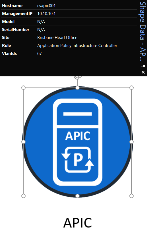
Shape Data populated on a dropped master.
Caption placement
Each master’s caption text sits below the icon, not over it. Sizes:
TxtPinX= Width × 0.5 (centred)TxtPinY= below the icon bodyTxtWidth= capped so long names wrap to two lines instead of bleeding sidewaysTxtHeight= TEXTHEIGHT(TheText, TxtWidth) (grows for wrapped text)Char.Font= Calibri,Char.Size= 8 pt,Char.Color= RGB(0,0,0) black
Dark-mode -DM variants use white caption text (RGB(255,255,255)) so the label remains legible on a dark canvas.
Searchable from the panel
Keywords are written per the empirically-derived search contract: each master carries the display name as its sole keyword, and the Master/@Prompt attribute is populated on every master. Repeating a common leading token (such as the group name) across every master would demote the entire stencil from Visio search, so keyword stuffing is deliberately avoided.
For details on how search works and how to enable Visio’s own search, see Enabling Search.
Native stroke geometry
The Cisco corpus is predominantly line-drawn: 287 of 486 icons contain stroke-only elements. A fill-only SVG converter would silently drop those outlines, leaving partial or invisible icons.
The pipeline emits true Visio line geometry with correct weight, colour, and dash pattern. Dashed boundary shapes such as Fabric Zone reproduce their dashed stroke in native Visio geometry rather than being rasterised or converted to filled outlines.
Dark-mode (-DM) variants
A number of Cisco icons are drawn in near-black inks (#121212 / #222931). On a light canvas they’re fine; on a dark theme or a dark-filled shape they become very hard to read.
V-1 ships 31 dark-mode -DM variants: a white-fill twin for each affected icon:
| Group | -DM count |
|---|---|
| Attribute | 7 |
| Endpoint (wireless) | 9 |
| Security | 11 |
| SD-Access | 2 |
| General | 1 |
| Total | 30 |
Search -DM in the Shapes panel to list all variants. The twin has every fill recoloured white (including the caption text) so it reads cleanly on a dark canvas while the original stays ideal for light backgrounds.
The recolour is real fill geometry, not an outline or effect, so the -DM icons scale exactly like any other master: no haloing or blobbing at small sizes.
ResizeMode = 2
Master.ResizeMode = 2 means when you scale a master after dropping it, the line weight and font size scale with it. Useful when you have a high-level system overview at one scale and a detailed component sub-diagram at another: the icons retain their proportions either way.
Double-click opens the text editor
EventDblClick = OPENTEXTWIN(): double-clicking any icon jumps straight into editing its caption, which is by far the most frequent post-drop edit.
Behaviour
Language = 1033(en-US, the canonical Visio language ID)- AlternativeText set to the display name: screen reader and accessibility tooling works correctly
Per-master contract
The exact configuration applied to every master is pinned as named constants in the build pipeline; nothing is inlined, and an automated verify step asserts the contract on every master in every build. Changes to the contract are deliberate and documented in Release Notes.